
Faketec v4 build
(beta version)
Introduction
Components
Tools and materials
Board preparation
Assembly
Testing
Advanced variants, gps, bme, etc
Cost
Ordering the faktec PCB
Introduction
Faketec is a great open-source project. It was created for the needs of another system, but the creators of the Meschore project prepared firmware for this microcontroller, so we can successfully use this board to build nodes in the Meschcore system.
There are several versions of this board. A higher version number does not mean it is better for your purpose, the higher versions simply have more features, which you may not need at all.
All versions use the same LoRa module and the same Pro Micro board.
The level of complexity increases with each newer version, and you really don’t need the V6 unless you want the built-in solar charging function.
I chose the V4 because it allows adding extra components such as a screen, BME280, or GPS, while at the same time the build is not too complicated and doesn’t require too many SMD components.
Each board from the Faketec series includes the “essential minimum components” required to achieve functionality (list below)
The fact is that the MeshCore mobile app is so well-designed that operating the board even in its bare minimum configuration is effortless. Starting from firmware version 1.12, temperature measurement is also available. The board is extremely energy-efficient, and in its “bare minimum” form it consumes an incredibly low amount of current. My box nodes can run for a week on a 2500 mAh battery, it’s insane!
Adding a temperature sensor or a small LED will reduce the box’s lifespan, the GPS will reduce it by about half.
Repeaters usually stay in place, so you know where you set them, GPS might make sense with a Companion Radio. I have one, but honestly, I’ve only used it a few times in the past month.
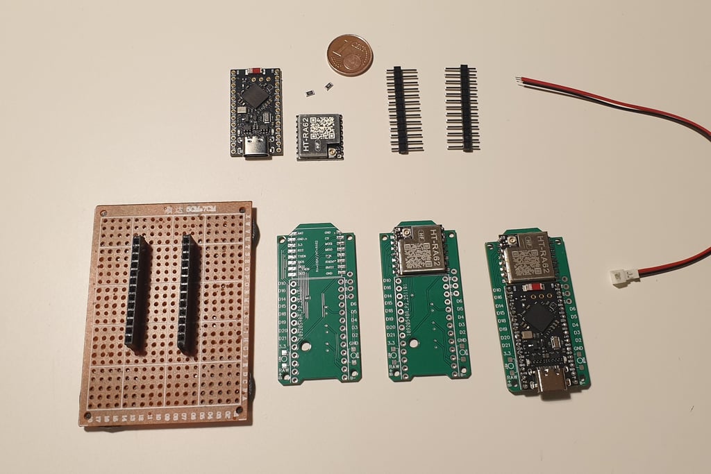
Components
Required parts
Faktec V4 board
LoRa module - HT-RA62
Pro Micro board
Recomended parts
R1&R2 - 2x1206 SME Resistors with equal resistance! (see notes bellow)
JST 1.25 pigtail for battery connection
Not required/ nice to have
Mosfets SI2312 - if you are planning to connect GPS or other funcions (plug n play, tested)
BME280 (plug & play, tested)
LCD (plug & play, tested)
ATGM336H GPS module (plug & play, tested)
buzzer (not tested)
mini buttons (not using)
LED diode (using only for clients)
NOTES:
There is misleading information online regarding the values of resistors R1 and R2. The comments often refer to systems other than Meshcore, and various values are suggested, such as 1MΩ and 680KΩ, or resistance ratios like 2:3 or others.
I recommend using two resistors with the same value of 1MΩ or higher in order to reduce the current flowing through the circuit.
Using resistors with different values makes it necessary to apply an ADC correction. This is not a simple task in the case of Meshcore, it requires modifying the firmware (for the companion radio) or using a CLI command for the repeater:
`set adc.multiplier x.xx`
where `x.xx` is a value selected experimentally, depending on the values of R1 & R2.
I built the entire first batch of boards using incorrect resistors, and after discovering the correct solution, I had to upgrade many of them, most of which were already installed in repeaters at various locations around the city.
Don’t make the same mistake I did 🙂
If you don’t need to read the voltage from the application, whether for a repeater or a companion radio, you can skip this entire part of the build.
These resistors are used only to measure the voltage, not to power the board.
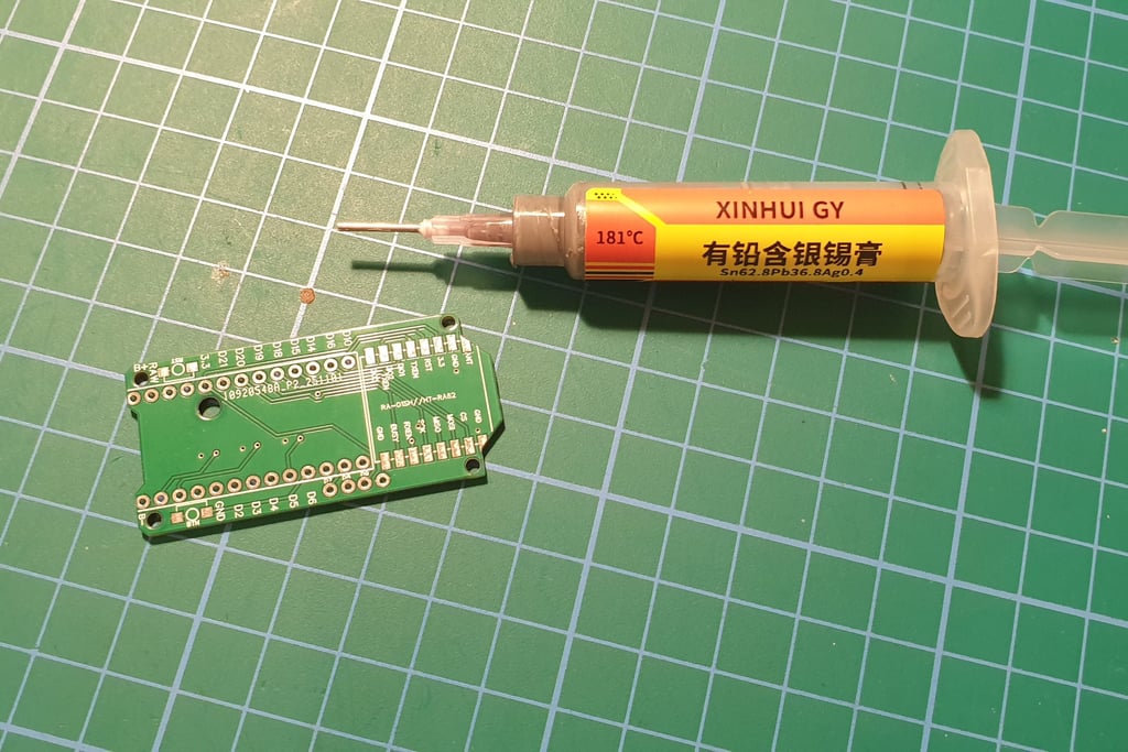
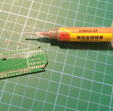
Tools and materials
Soldering Iron + solder
Hot plate ( nice to have) + low temperature soldering paste (150-180C)
Magnifying glass.
Wire cutting pliers.
Good lighting.
Vacuum cleaner.
Eye protection (The cut pieces of wire from the board will fly everywhere, watch out for your eyes!)
PC with internet access and a USB-C cable for flashing the firmware.
Precision tweezers.
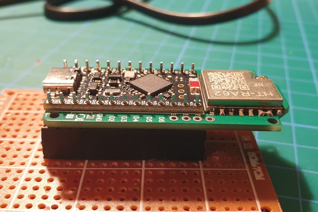
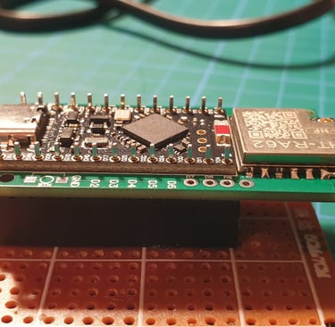
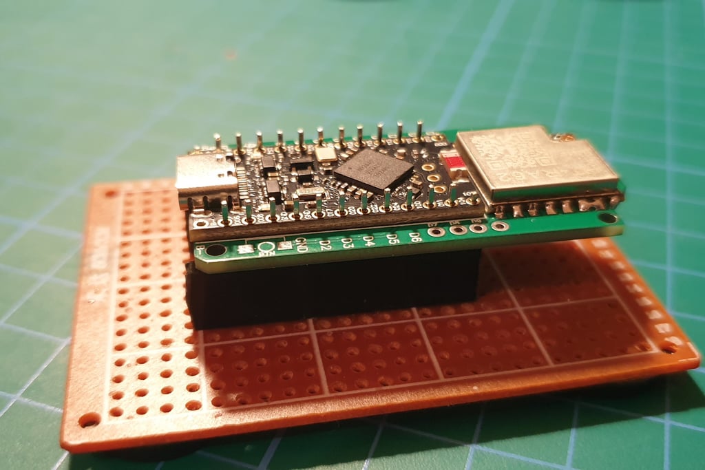
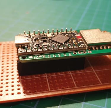
A holder or base, something that allows you to hold the board comfortably. I made one from a prototype board, the standard spacing allows the PCB to sit securely and stably.
cleaner (like isopropanol)
Board preparation
connect the promicro board to pc and update the bootloader (bootloader OTA tutorial)
open the web flasher, find promicro, (select any type of node, this is just iniitial flash) and perform: Enter DFU>Erase>Flash
if the flashing was successful, promicro can be soldered
clean he soldering pads on faktecec pcb (isopropanol)
now you can move to assembly section
Assembly
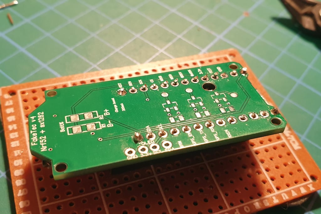
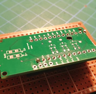
The individual stages of assembly and the components needed for the board in the “bare minimum” version.
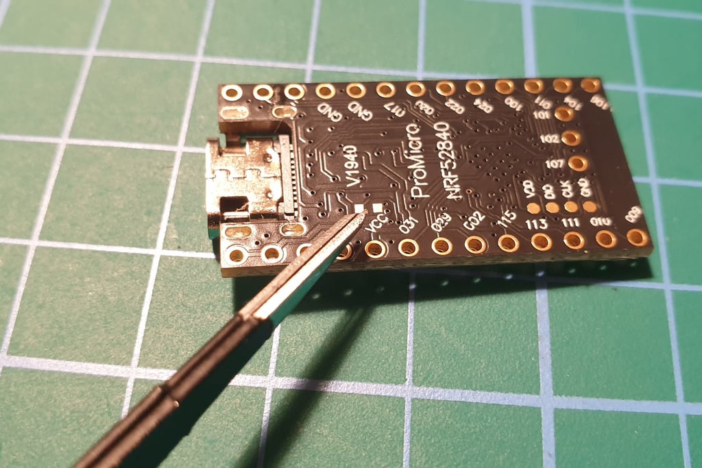
The Pro Micro board has the option to charge the battery at two current levels: 100 mA or 300 mA. To enable the higher charging current, you need to solder together two small pads on the bottom side of the board.
It may seem simple, but the pads are small enough that it can be tricky. After various attempts, the most effective method turned out to be this.
First, place two small dots of solder on the pads, then position the pre-tinned thin wire across them and heat each side until it bonds. After that, trim excess wire so the jumper fits properly within the hole in the PCB.
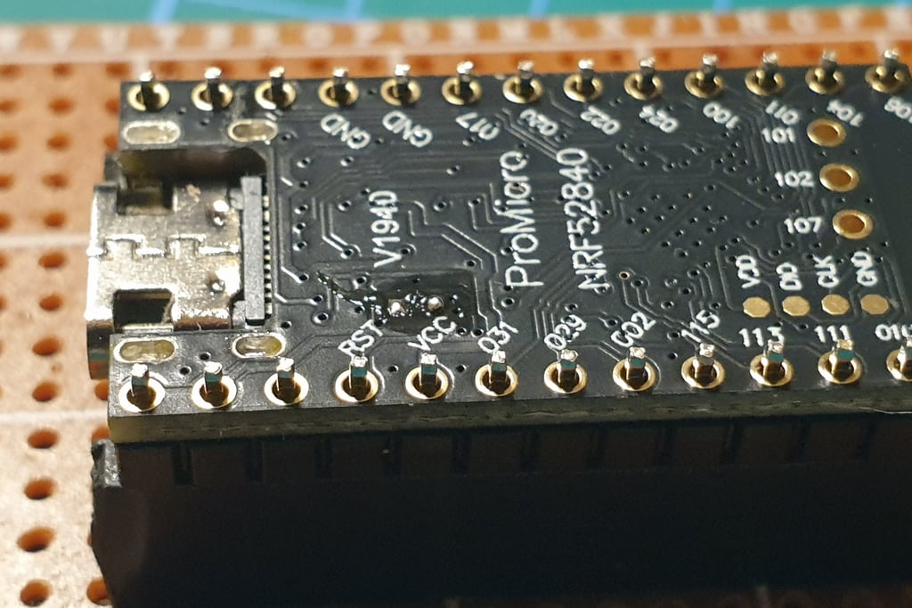
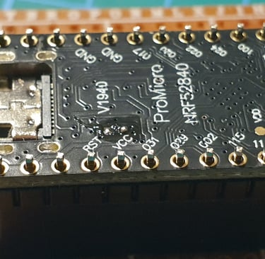
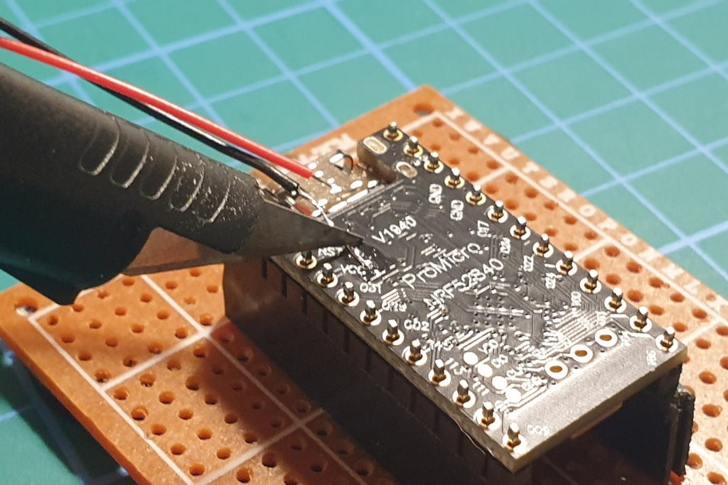
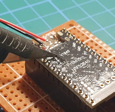
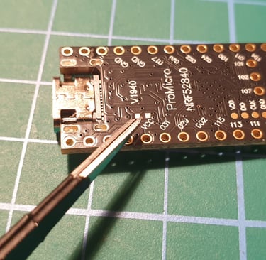
It should look something like this.
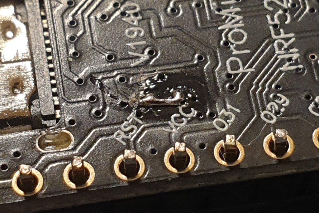
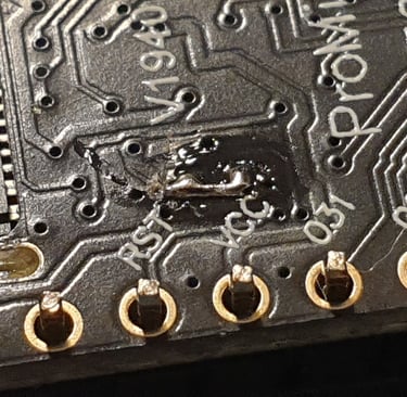
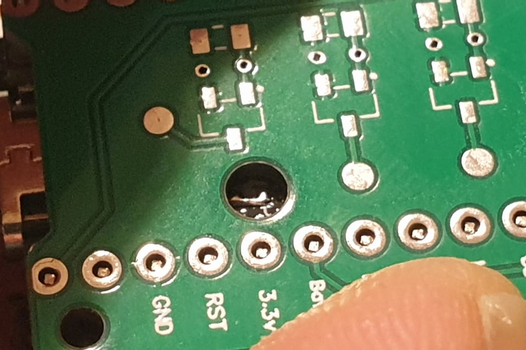
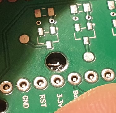
The boards should be assembled in such a way that there is no gap, and the jumper fits entirely within the hole in the PCB.
The next step is to solder the LORA module. If you plan to build a larger number of boards, it may be helpful to buy a small heat plate (around 10 euros), as it will speed up the process. However, the connections will still need to be checked for correctness afterward.
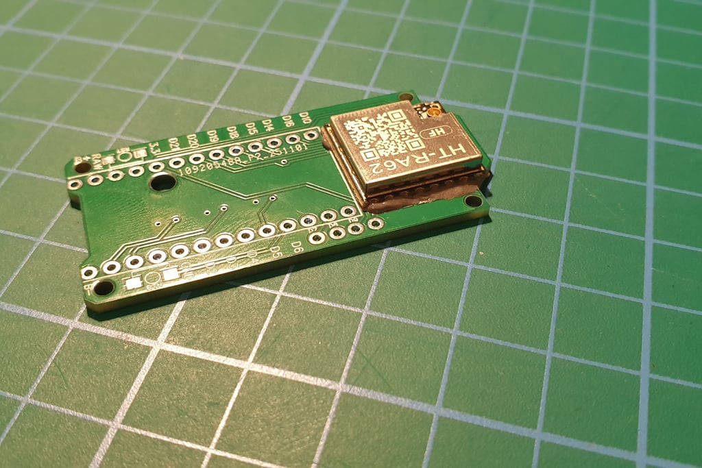
Place the radio module on the board in the correct position.
While the plate is heating up, apply solder paste to the pads underneath the LORA module.
Then heat the prepared board. The hottest spot is in the center, so place the module near the center of the heat plate. After a short while, the solder paste will start to melt, and the component should self-align, floating into the correct position on the molten solder.
When all the solder has melted and the module is in the correct position, you can gently lift the board with tweezers and let it cool. At this stage, while the solder is still hot, the module is floating and can shift, so handle it very carefully, without tilting the board. A crookedly soldered LORA module is difficult to fix.
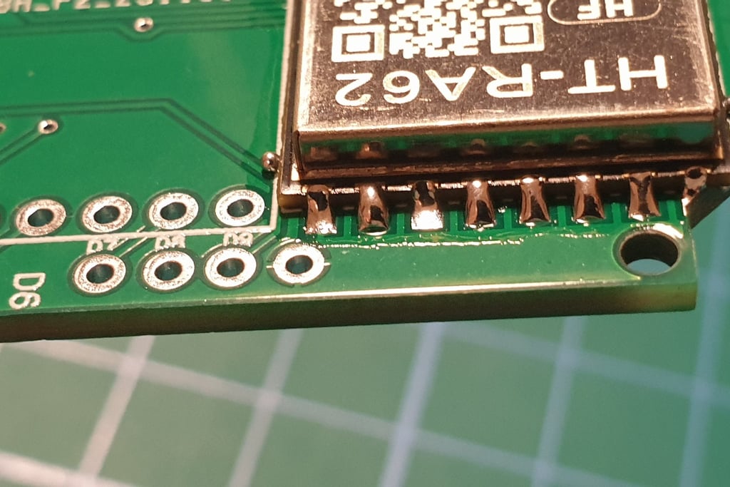
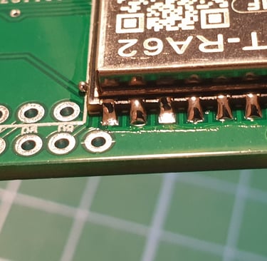
Remove any solder defects and small debris like that tiny ball. If you don’t clean this up properly during soldering, you’ll have to deal with it later. A magnifying glass will help, nspect every joint and, if necessary, fix it with a soldering iron. Small balls like that usually just need a gentle nudge with a fingernail or tweezers.
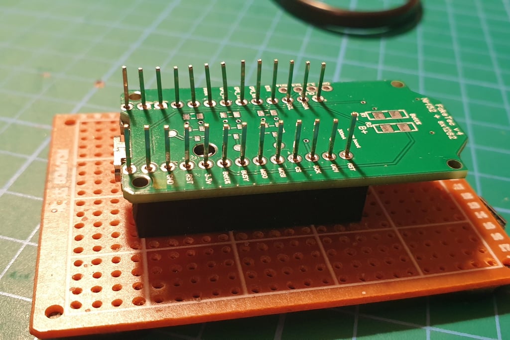
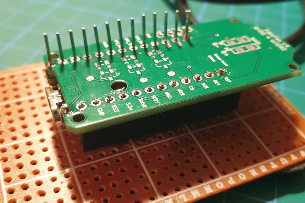
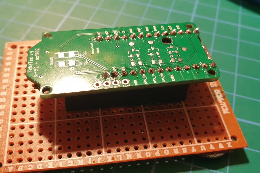
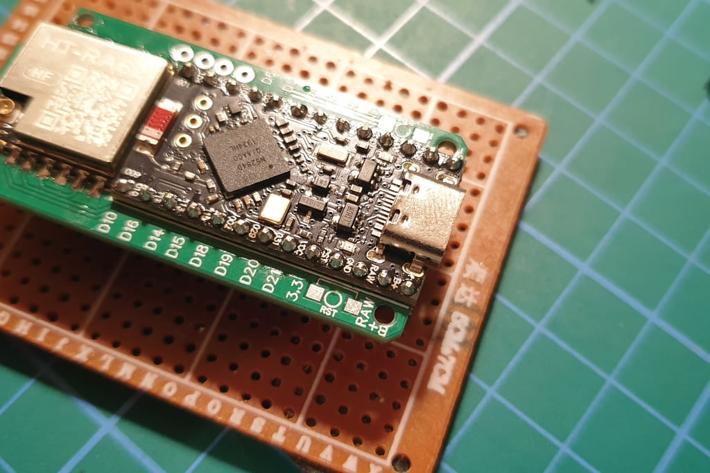
The next step is to connect the Pro Micro and Faketec board. I made a holder that helps position the boards correctly and makes soldering easier.
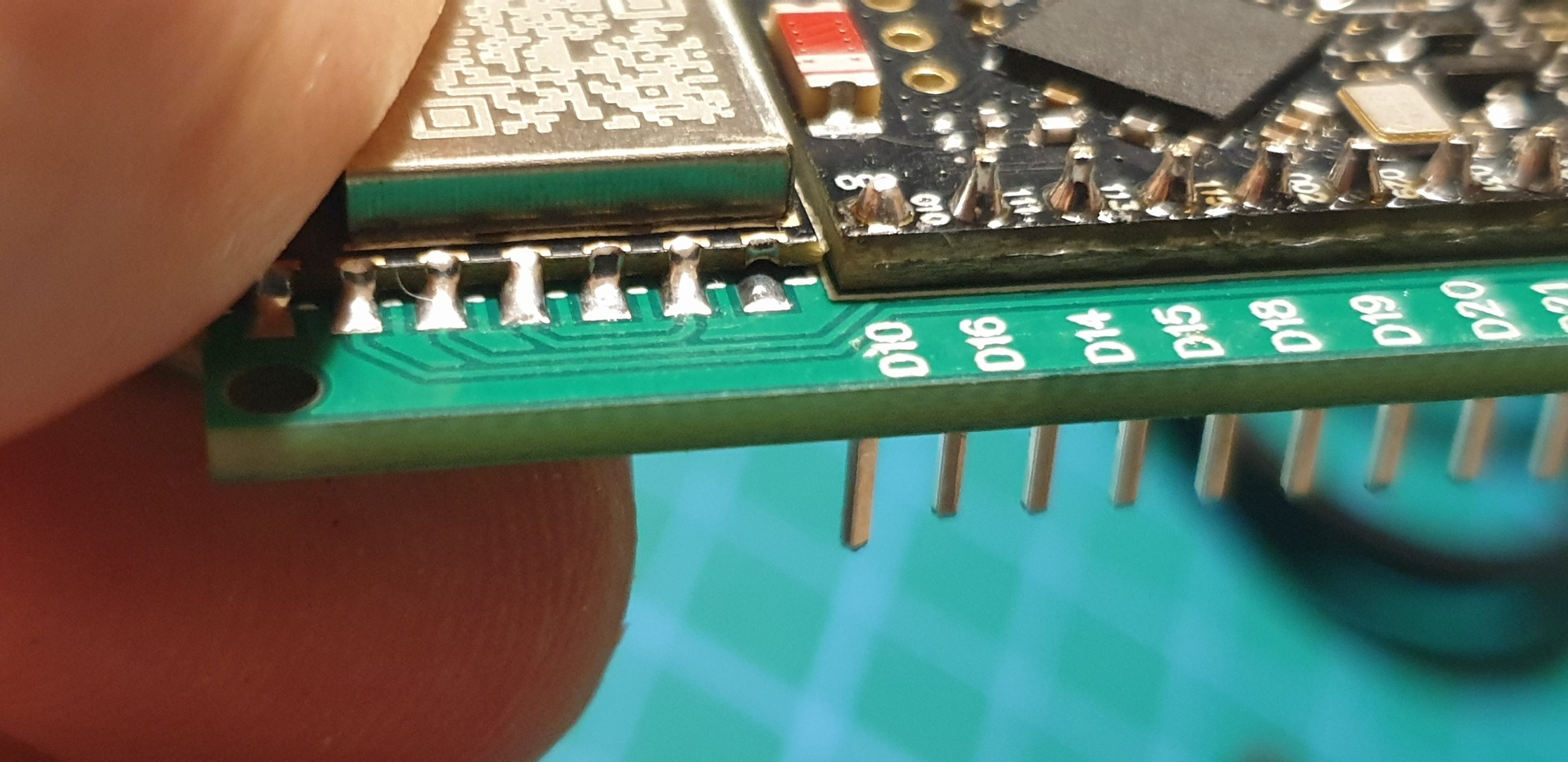
Press the end pins so they sitk out about 1 mm above the board. You don’t have to do this, but I like the board to have a low profile, as it makes later installation in the enclosure easier.
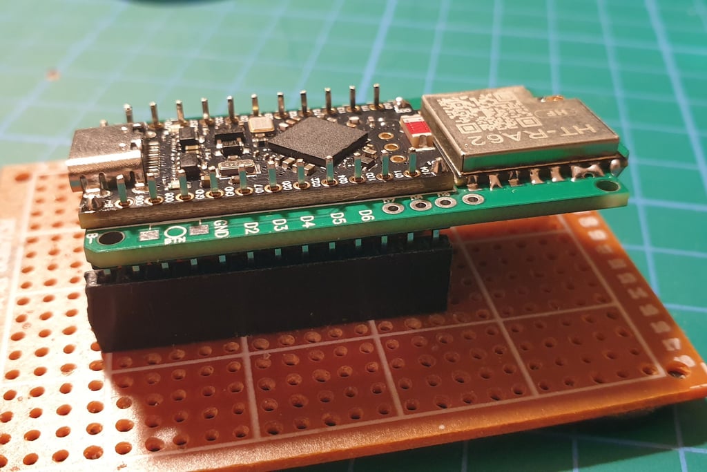
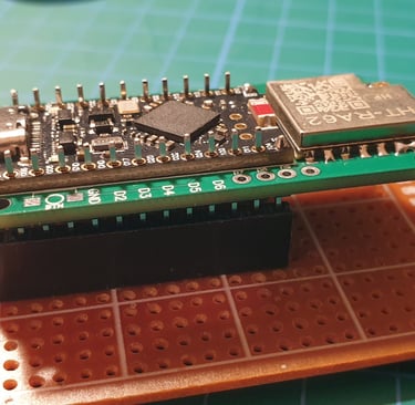
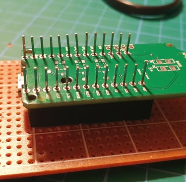
Solder the two outermost pins first, then adjust the remaining ones so they are aligned properly and evenly positioned before soldering the rest.
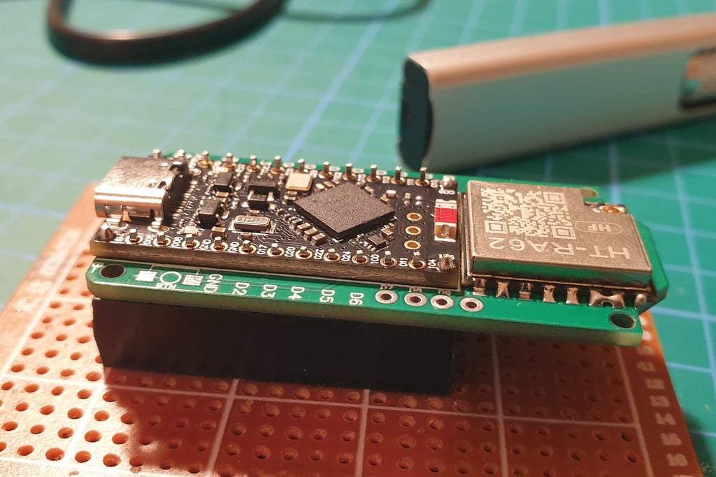
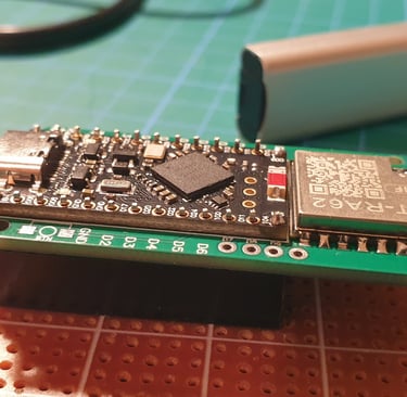
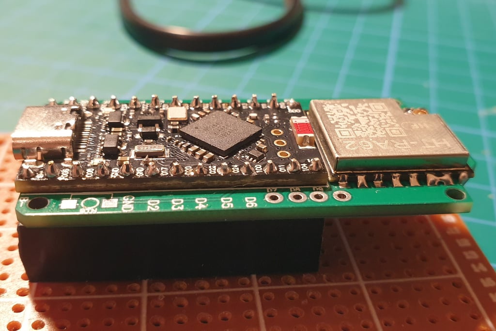
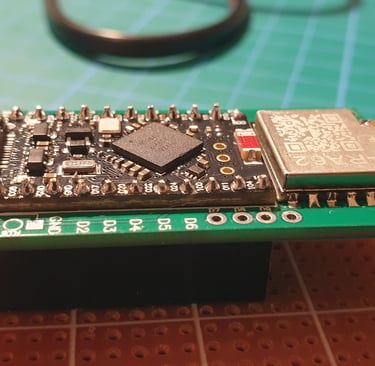
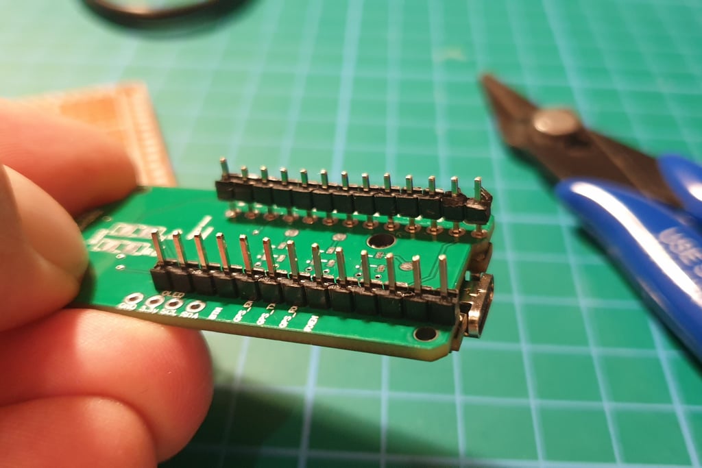
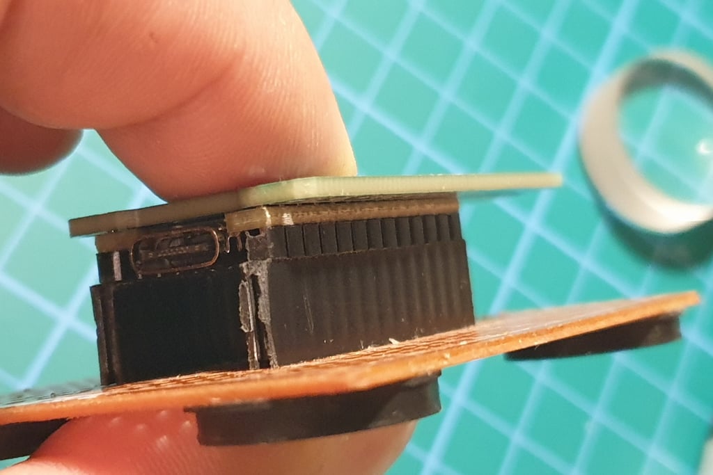
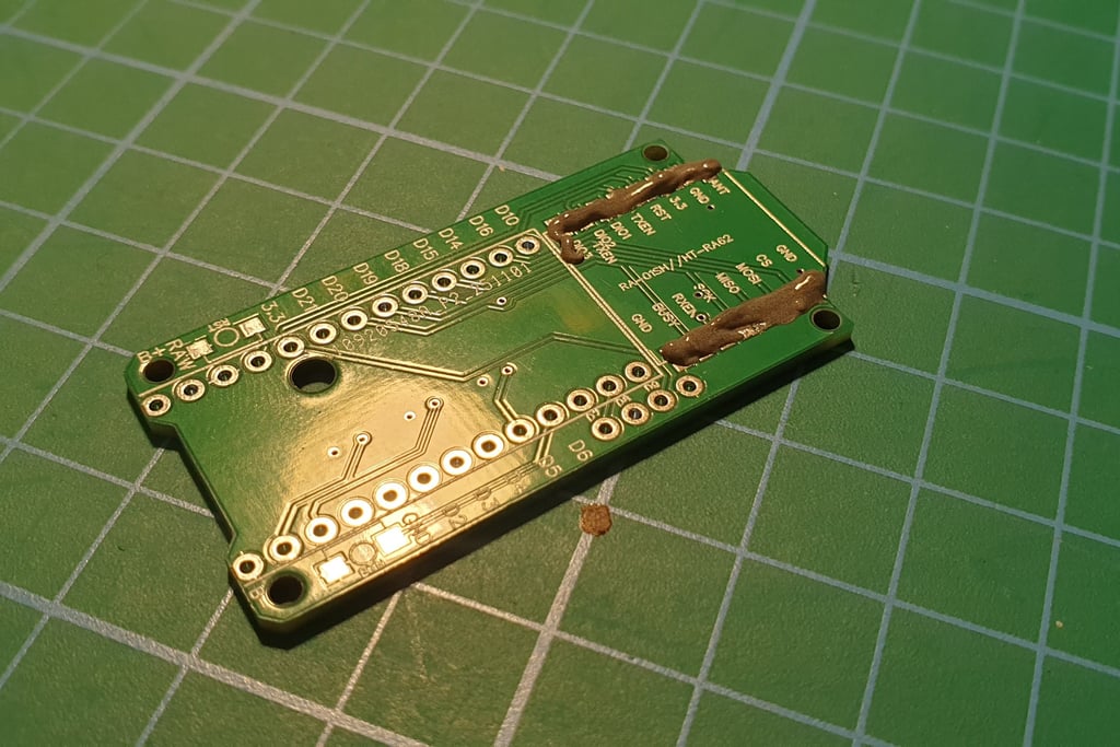
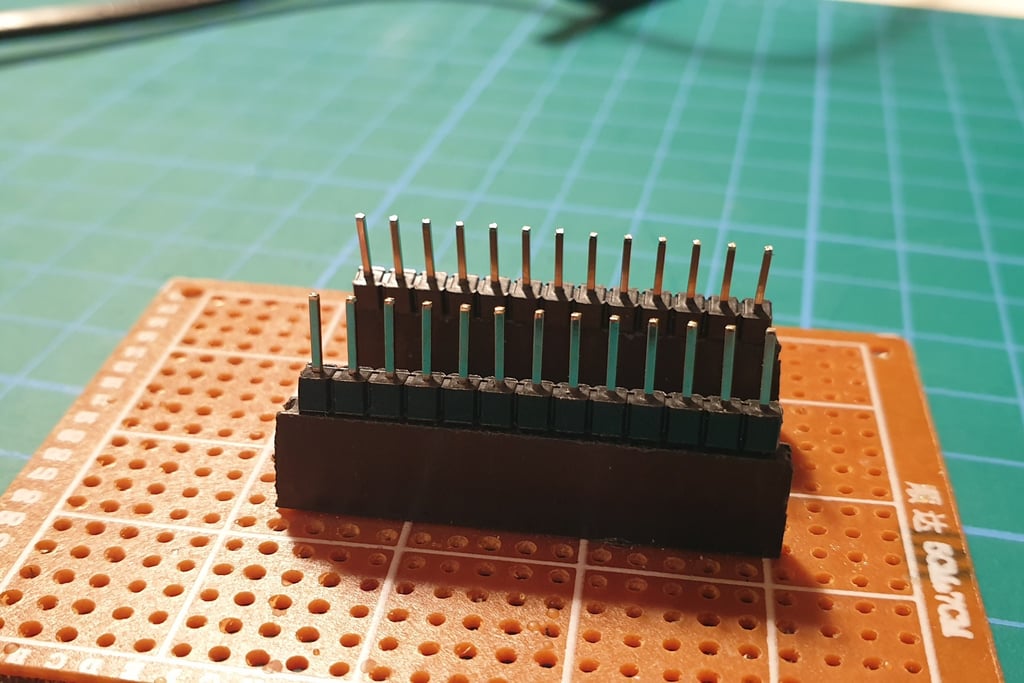
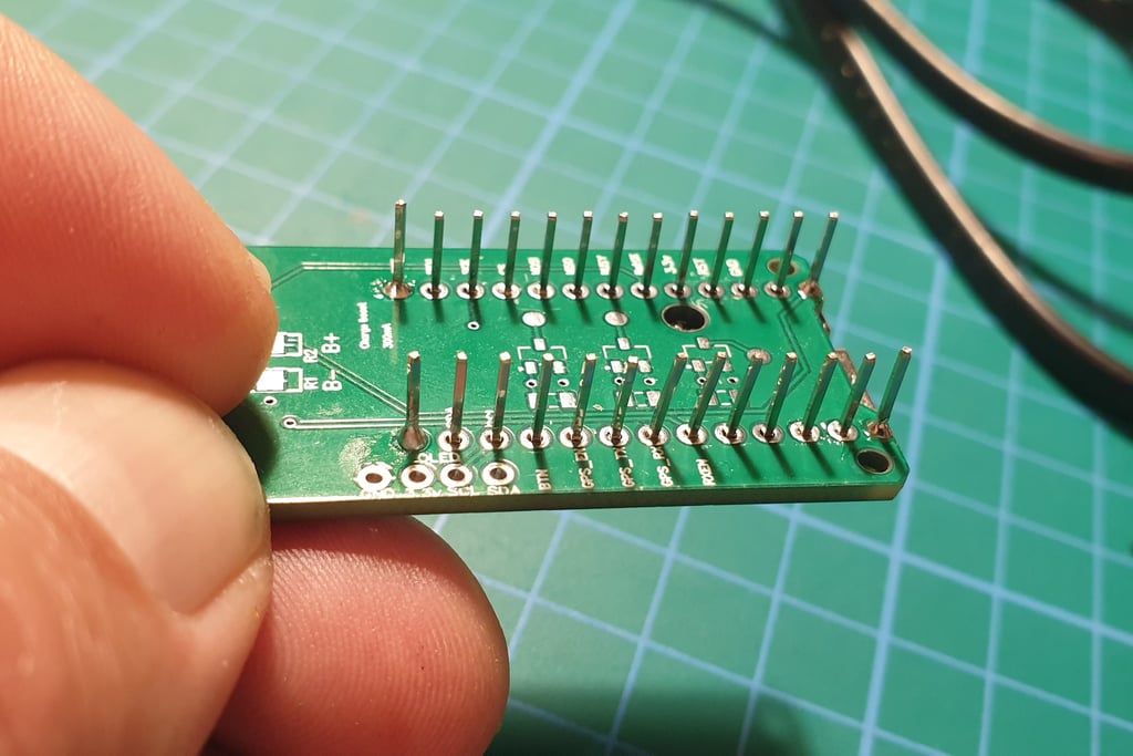
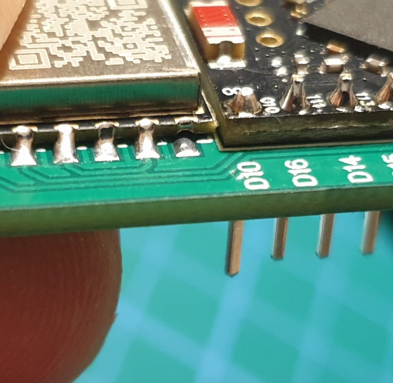
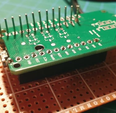
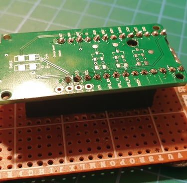
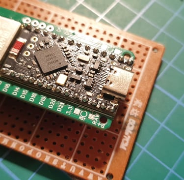
Now let’s move to the other side of the board. After removing it from the holder, you’ll see something like this.
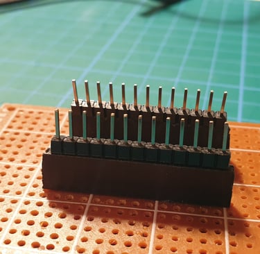
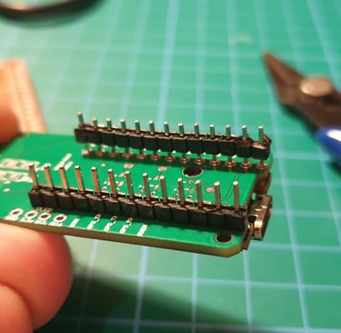
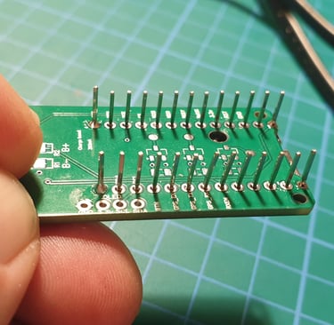
You need to remove the plastic parts. The easiest way is to gently pry them off with pliers and slide them off. Do not cut the pins yet, we’ll get to that in a moment. After removing the plastic parts, you should see this.
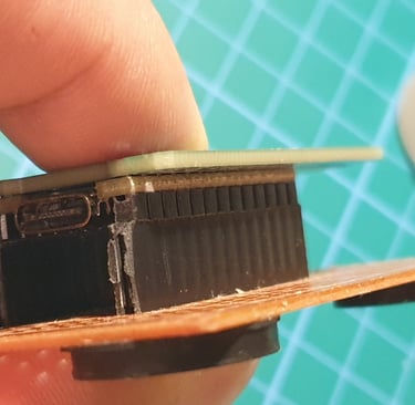
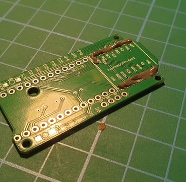
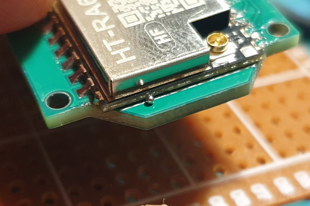
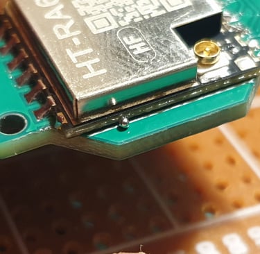
Now solder the outer pins, pressing the boards firmly together. After soldering each pin, wait a moment for it to cool before moving on to the next one. Thermal stress can cause the boards to shift out of alignment.
If, after soldering the first four points, the boards are not perfectly flat, reheat the joint and press them together again. You should end up with something like this.
Another example of an imperfection when using a hot plate is a hollow (cold) solder joint like this. Such a defective joint must be identified and corrected during the inspection stage.
Cut the pins with pliers, trying not to scratch the board. Be careful, clipped wire ends can fly off in any direction, so make sure to wear eye protection. My cutters are not the best quality, so the trimmed pins don’t look perfect, but fortunately the final soldering will improve the overall appearance.
Solder the remaining pins.
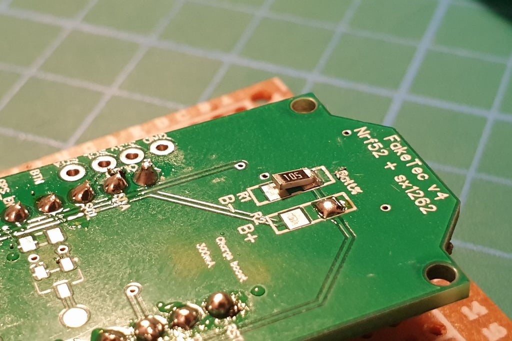
Let’s move on to the next part: installing R1 and R2. They are not strictly required, but they are useful. Thanks to them, the application will display the correct voltage, which is especially helpful for battery-powered nodes.
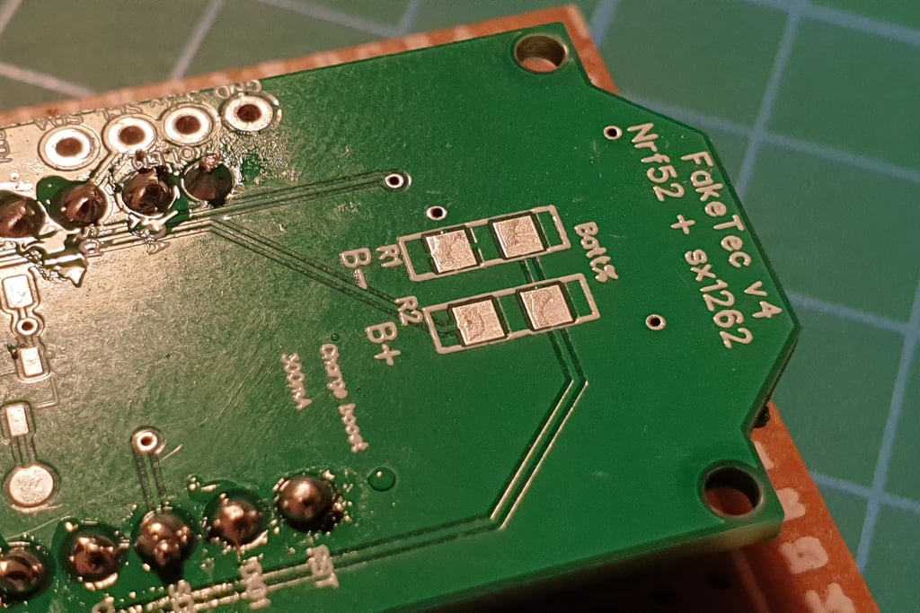

Apply a small amount of solder to the pad on one side.
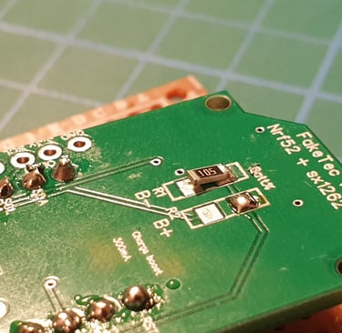
Holding the resistor with tweezers, solder one end to the board.
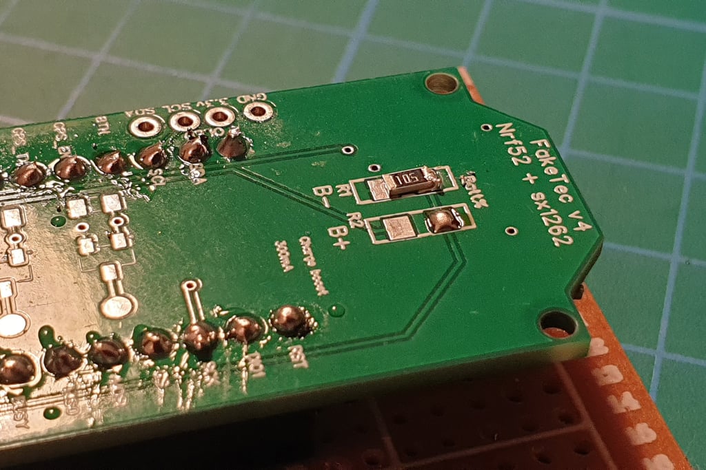
Press the free end of the resistor and touch the soldering iron to the already soldered end. This will allow you to lay the resistor flat on the board.
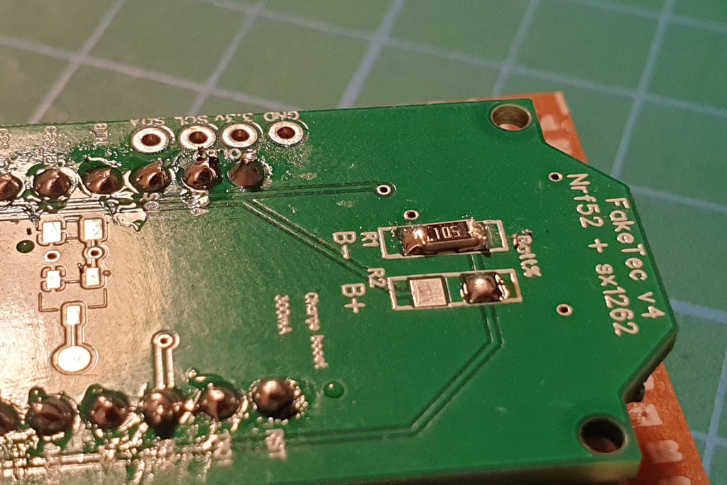
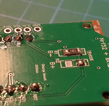
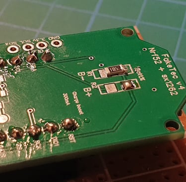
Solder the other end using a small amount of solder.
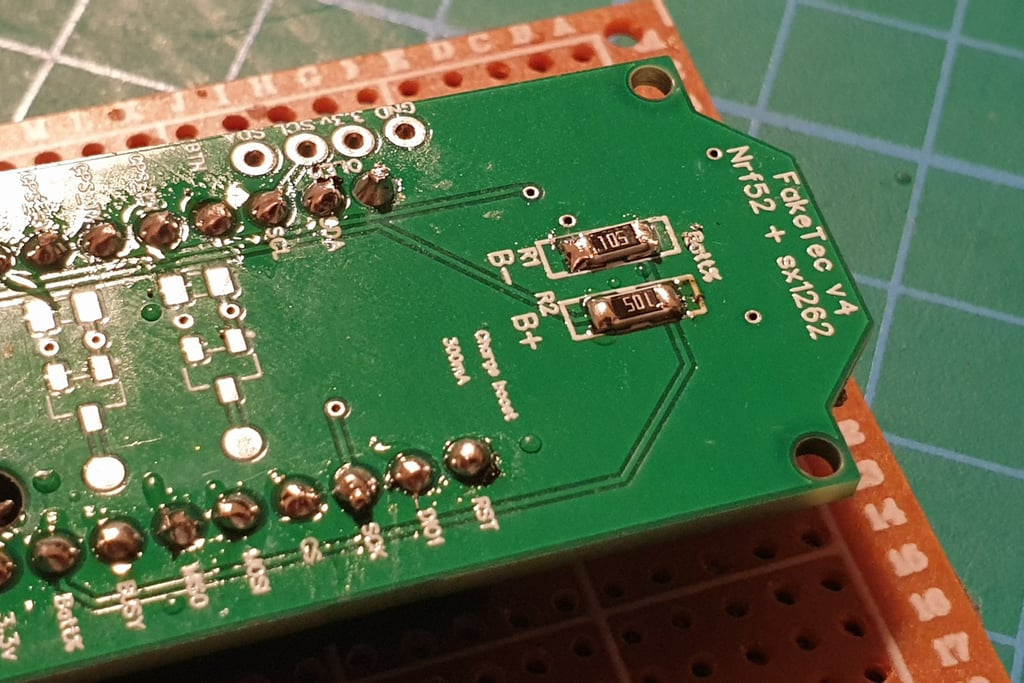
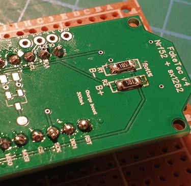
Repeat the process with the second resistor.
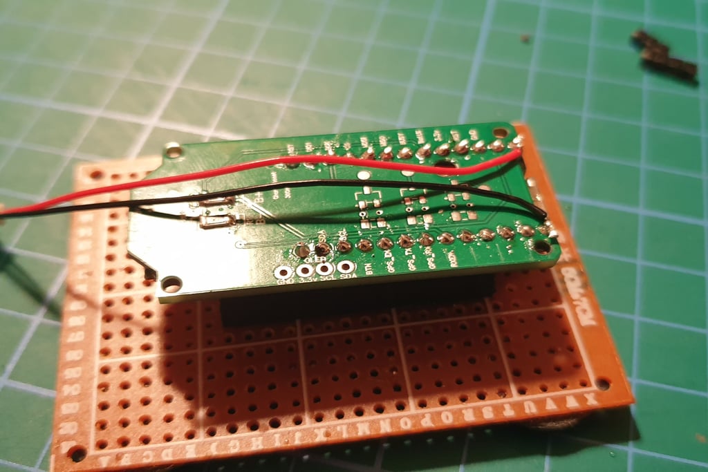
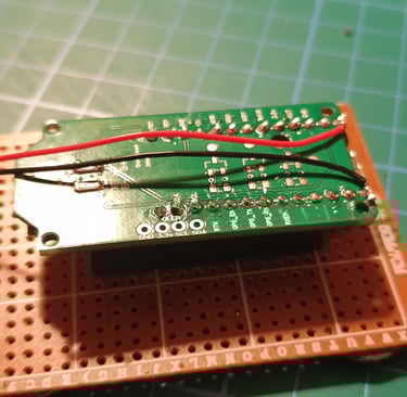
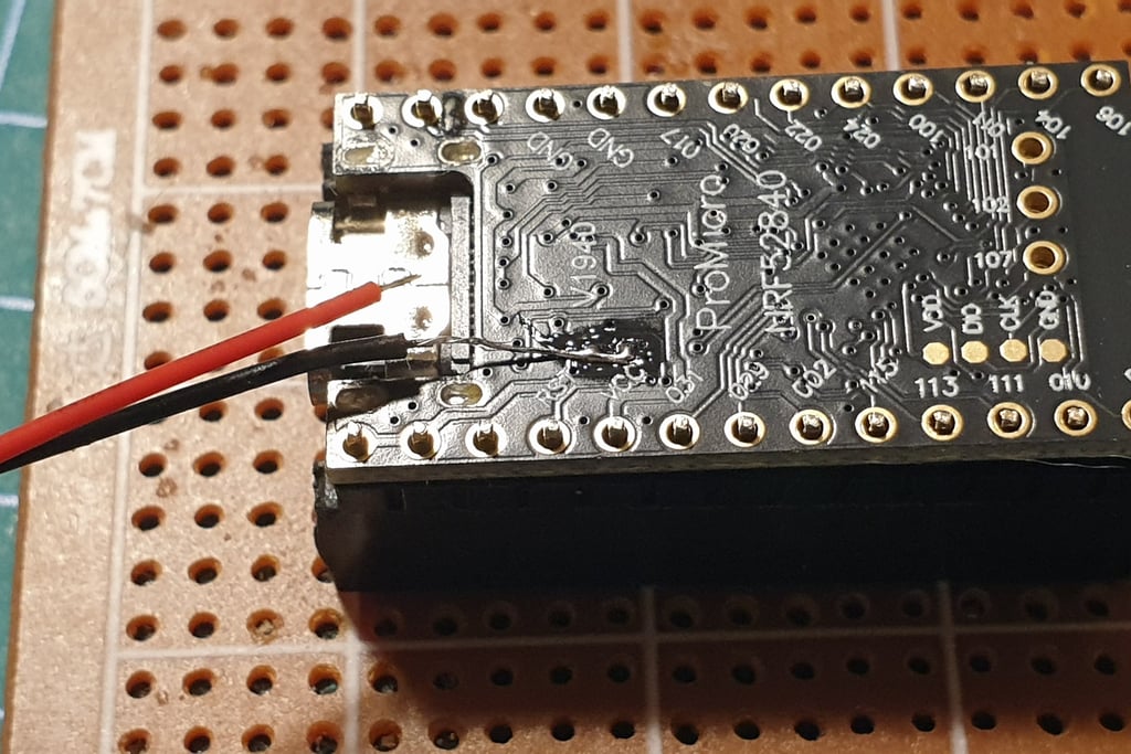
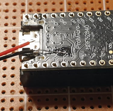
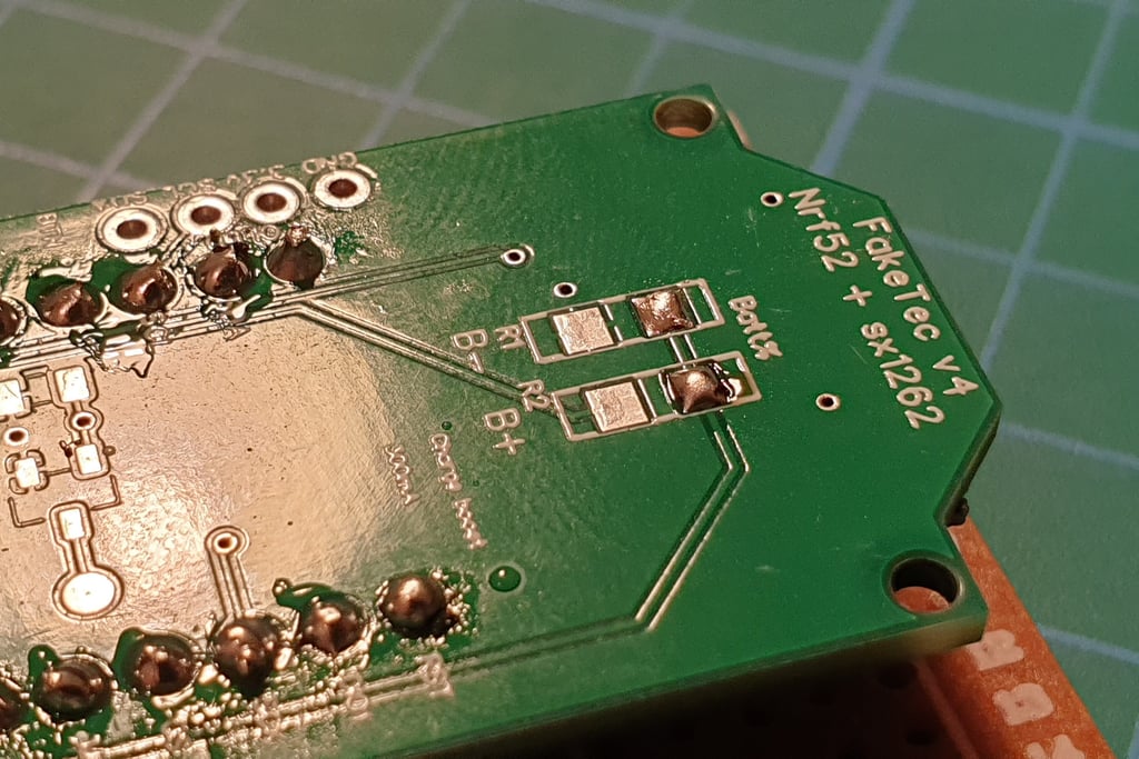
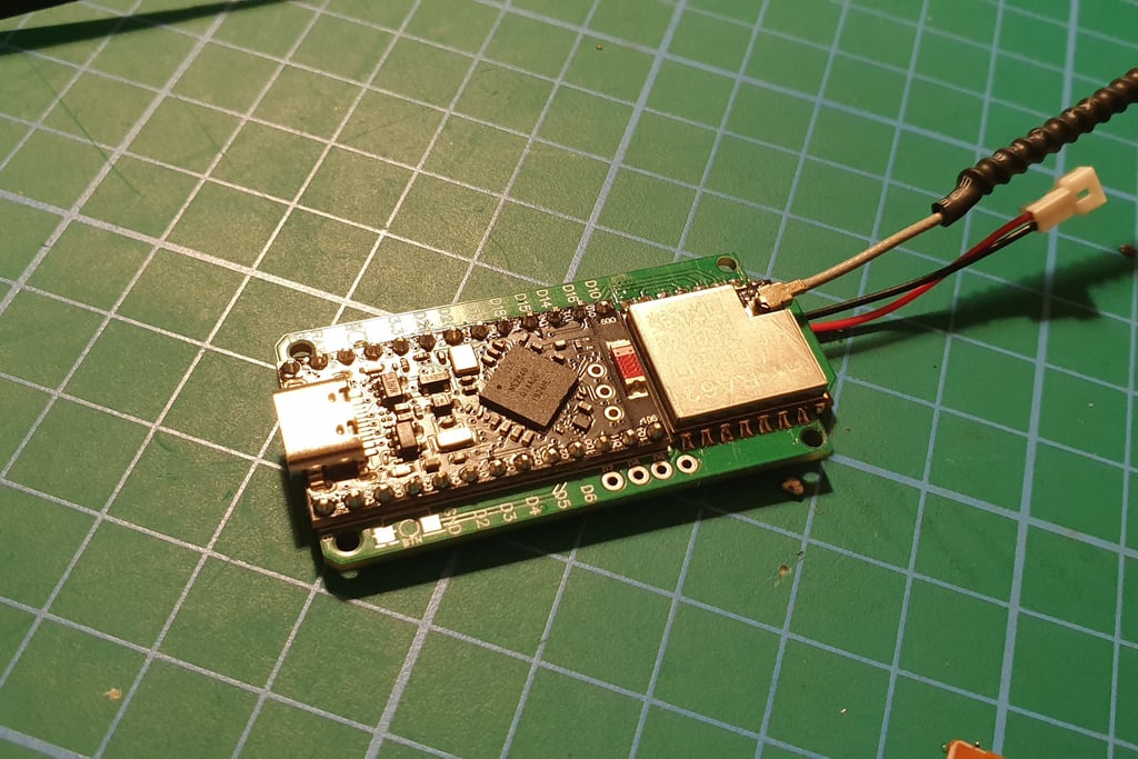
Add the power wires.
Pay attention to the polarity, the pin labels are on the other side of the board, near the USB connector.
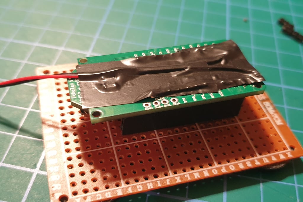
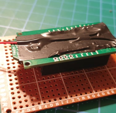
I usually add insulating tape or capton on the underside to protect the wires and prevent short circuits. It may not look very neat, but hey, it’s not a beauty contest!
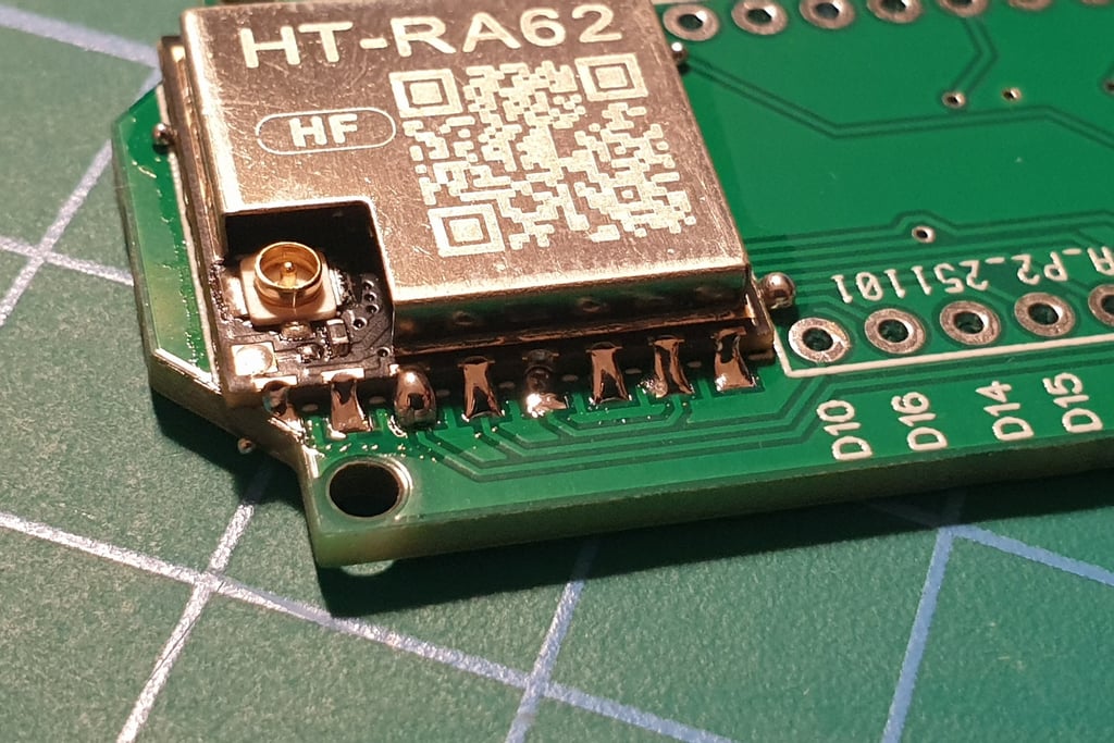
OK, we’re almost done. Perform a final visual inspection of all, attach the antenna, and proceed to testing.
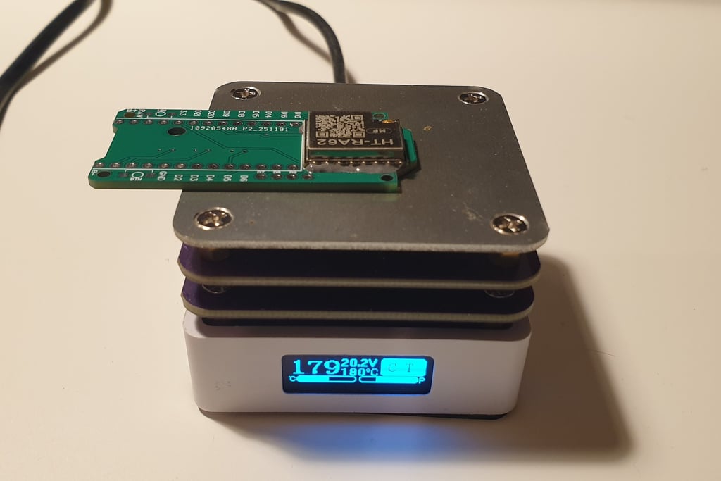
Testing
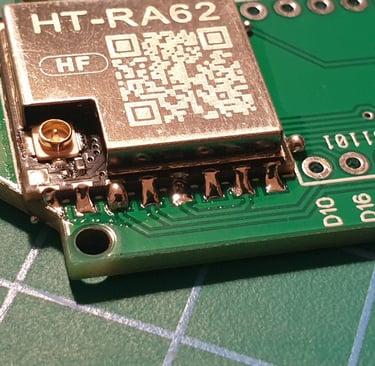
The most important thing: after soldering the LORA module and Pro Micro, every time you power up the board, it must be done with the antenna connected or with a dummy load attached to the IPX connector on the LORA module.
Perform a visual inspection of all soldered points (using a magnifying glass). Look for shorts, incomplete soldering, or foreign objects like pieces of wire. The board should be clean before testing, and the power cables must be connected to the correct pins. If you use a hot plate to solder the LORA module, "touch" each joint with a soldering iron, often there is either too little or too much solder, and at low temperatures, the joint can crack!
After the visual inspection, connect the antenna and the board via USB to PC and upload the firmware again. You need to check both Bluetooth and LORA, so using Companion BT seems like a good choice. It is nice to have another phone or tablet with meshcore app to do the tests, not to mess with your main phone/companion
A good practice is to perform tests on a non-primary channel or frequency, because such tests often creates mess on the map. When you flash 10 boards and 10 virtual clients or repeaters, they can appear on the map. It’s also advisable not to provide GPS coordinates during tests. They shouldn’t appear on the map at all in that case.
If there’s no smoke or strange smells, and you can see messages and connect to the board via BT or radio, there’s a good chance it worked ;-)
Congratulations on building your first Faketec board!
Advanced variants, gps, bme, etc
inpr
Cost
The cost of building a board mainly depends on the changing prices of components in online stores. It may also depend on the number of boards you plan to build. If you include the cost of purchasing tools, the price may increase. However, you can expect a price of below 10 euros for a complete board (in the basic version, without components that are not essential for operation, such as GPS or BME280).
The prices of small electronic components are just a few cents each, but you usually need to buy them in larger quantities. Often, for small parts like resistors or switches, it’s better and faster to buy them at a local electronics store (there is an excellent one in Alcobendas!) than to order huge packages from the other side of the world.
0.3 EUR - PCB (when ordering several dozen, including shipping)
4-5 EUR - RA-HA62 Lora module
2-3 EUR - promicro board
0.1 EUR - resistors
0.1 EUR - JST pitgail
Additional items
4-5 EUR - ATGM336H GPS
1-4 EUR BME280 (many variants of the board)
0.1 EUR SME buttons
0.1 EUR Mosfets SI2312
0.1 EUR resistors for mosfets
Ordering the faktec PCB
Boards can be ordered from a factory that has the technology to manufacture printed circuit boards and offers small-batch production.
I personally used the service at jlcpcb.com
From the Faketec project page on GitHub, you first need to download the gerber files.
Create an account on your chosen PCB manufacturing site, then start a "new project" and upload the gerber files.
After placing the order, you just need to wait a few weeks for delivery (the time depends on the shipping option).
When ordering small quantities, shipping costs usually exceed the price of the boards. Another thing to be aware of: when ordering from outside the EU, you can expect customs fees.
It’s worth considering a shipping option that includes customs fees paid upfront to avoid any surprises.
© 2025. All rights reserved.